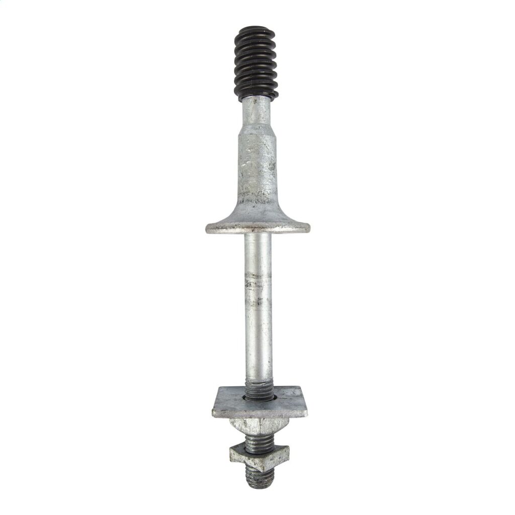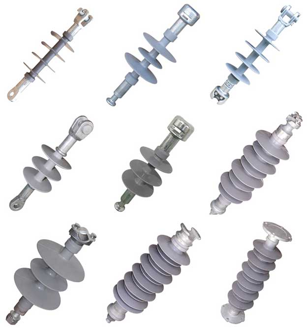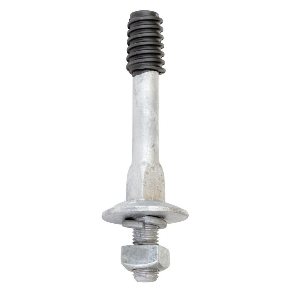
An insulator pin is a crucial instrument for supporting and isolating conductors from the support framework. It features a single, formed shape with a grooved or looped top that holds the conductor. Its major role is to provide insulation between the transmission line conductor and the support structure. This prevents electricity from passing through the tower or pole. It also ensures that the current remains within the conductor. Insulator pins also provide mechanical support for conductors. They help to spread the conductor’s weight along the transmission line. They help conductors survive mechanical loads caused by wind, ice, and temperature variations. Insulator pins are from porcelain, glass, or composite materials.
Common characteristics of an insulator pin
Insulator pins have various characteristics that ensure their efficiency as electrical insulation. The characteristics work together to ensure that transmission lines run reliably and efficiently. This is by providing electrical insulation and mechanical support for the conductors. The following are the usual characteristics of an insulator pin.

- Material composition – the insulator pins are from porcelain, glass, or composite materials. They provide excellent electrical insulating resistance and mechanical robustness. This is necessary to resist the extreme environmental conditions.
- Pin design – this refers to the main body of an insulator pin, which might be cylindrical or elongated. This design makes it easier to install and mount onto support structures.
- Weather resistance – the pins can withstand a variety of weather conditions. This includes severe temperatures, humidity, UV rays and pollution.
- Creepage distance – they also include devices to avoid electrical arcing between wires.
- Insulator discs – they may include one or more insulator discs or shells stacked on top of one another. The discs provide extra electrical insulation and are often designed to shed water and pollutants. This helps to reduce surface leakage currents, which could impair the insulating qualities.
- Mechanical fittings – pins may contain metal fittings such as caps, bolts and washers. They aid in securing the conductor to the insulator and attaching the insulator to the support structure. They can also give mechanical stability and maintain the integrity.
- Corrosion resistance – insulator pins are from materials that are resistant to corrosion. These include stainless steel hardware or corrosion resistant coatings. This is to ensure long-term reliability and performance. Load bearing capacity – the pins are able to withstand the mechanical loads from the weight of the conductors and external forces. They also have designs to maintain the structural integrity and electrical insulation.
Designs of the Insulator Pin
The insulator pin is simple in form, with several parts that play important roles in its functionality. The design is critical for assuring the efficacy of electrical insulation. Furthermore, the designs are mostly built to assure reliable and efficient power transfer. The following is a comprehensive design of the insulator pin.

- Pin structure – the primary body of the insulator pin, which is a cylindrical structure composed of various materials. This structure makes it easier to install and mount onto the support structure.
- Discs – Insulator pins contain one or more insulator discs stacked on top of each other. The discs provide extra electrical insulation and have designs to shed water and pollutants. The form of the discs enables for the minimization of surface leakage currents. They also contribute to insulation performance.
- Metal fittings – pins may include caps, bolts and washers. They aid in securing the conductor to the insulator and attaching the insulator to the support structure. They also provide mechanical stability and protect the transmission line.
- Creepage distance – The design may contain a creepage distance to prevent electrical arcing between conductors. Creepage distance refers to the needed distances along an insulator’s surface.
- Corrosion resistance – insulator pins are corrosion resistant and can survive a variety of environmental conditions. This includes severe temperatures, humidity, UV rays and pollution.
- Load bearing – the pins have designs to endure mechanical loads from the weight of the wires. It contains structural reinforcements and appropriate materials. This is to ensure that the insulator pin can hold the conductors.
- Mounting mechanism – the insulator pin comes with a mounting mechanism. This provides a secure attachment to the support framework. This can be through a bolted connection or a clamping device. This holds the pin in place and supports the transmission line.
What is the physical structure of the insulator pins.
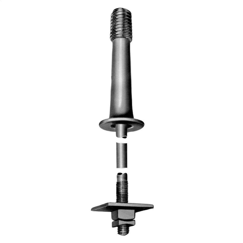
The pin insulator’s structure consists of several critical components. They have designs for electrical insulation and mechanical support. The structure consists of up of the pin body, discs and contamination prevention measures. They collaborate to offer electrical insulation and mechanical help. The following diagram depicts the structure of an insulator pin.

- Groove or loop – this is where the conductor wire rests and can be a U-shaped groove that cradles the conductor. It can also be an eye or loop that encircle the conductor, providing extra support for larger conductors.
- Pin body – the pin body is a cylindrical device that serves as the insulator’s core support. It also gives the means to attach to
- Threaded shank – this is the most frequent way to mount the insulator pin. The threads screw into the threaded hole on the support structure, ensuring a firm and stable hold.
- Tapered shanks – these use a wedge-shaped construction to fit into a hole in the support framework. They may employ hardware such as bolts, clamps, brackets or other fastening methods.
- Weather contamination protection – the insulator pin’s construction contributes to its resistance to contamination. The materials utilized are resistant to UV rays, dampness, pollution and other conditions.
- Reinforcements – the insulator pin’s construction includes extra reinforcements. They contribute to increasing its mechanical strength and resilience. Ribs, flanges, and other structural features serve to disperse mechanical loads.
Technical Specifications for Insulator Pins
The technical criteria for an insulator pin differ depending on several factors. These include voltage rating and design specifications. Manufacturers should give specifications and criteria to guarantee that the chosen insulator meets the necessary technical requirements. It is also recommended to check reliability, cost and ease of maintenance. The following are some common technical standards for insulator pin selection.
| Minimum Failing Load | Ref. No. | A | B | C | D | E | F | G | X | Y | |
| 11Kv | 540kg | UTX-165 PIN | 165 | 40 | 24 | 25 | 20 | 5 | 12 | 150/50 | 44 |
| 22kv | 1080kg | UTX-230 PIN | 230 | 50 | 24 | 38 | 24 | 5 | 12 | 150/50 | 44 |
- Voltage rating – Insulator pins have ratings for various voltage levels, which determines their function. Insulator pin voltage ratings typically range from low to high (11kV to 765kV).
- Mechanical strength – this is an insulator pin’s ability to endure mechanical loads. Wind, ice, and conductor weight are all potential sources of stress. Specifications include the greatest permissible load, bending strength and impact resistance.
- Corona performance – this refers to the insulator pin’s capacity to suppress corona discharge. Corona performance specifications include corona onset voltage and corona extinction voltage.
- Temperature rating – Insulator pins may have temperature ratings that state the greatest and least temperatures at which they may work safely.
- Dimensions and mounting – the requirements include length, diameter and thread size of the insulator pin.
- Material – The pins are from a variety of materials, depending on mechanical strength, electrical insulating qualities and environmental resistance.
- Creepage distance – the requirements ensure that the insulator pin retains electrical insulation even in extreme weather conditions.
- Pollution performance – Insulator pins can survive pollution flashover, which happens when pollutants accumulate on the insulator surface. The standards ensure that the insulator pin can function in contaminated settings.
Frequently asked questions
Insulator pins are typically constructed of porcelain, glass, or composite materials such as polymer. These materials have good electrical insulation resistance, mechanical strength, weather resistance and longevity, making them ideal for outdoor transmission line applications.
Insulator pins install at regular intervals along the transmission line, and each pin supports one or more conductors. They attach to crossarms, poles, or towers using the necessary hardware. They have spaces based on the electrical and mechanical needs of the transmission system.
Consider the line’s voltage rating, climatic conditions and mechanical needs. When selecting insulator pins, keep cost in mind as well as unique application needs.