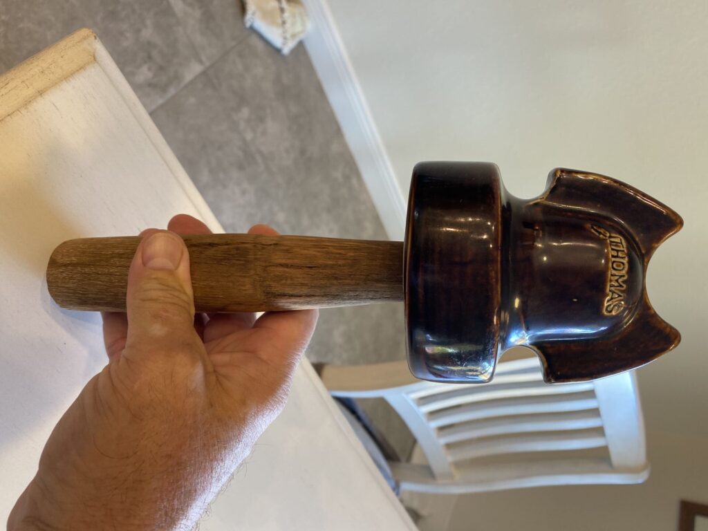
A crossarm pin is a component used in power transmission and distribution systems to secure insulators or other devices to secure the crossarm of a utility pole. The pin serves as a mounting point for insulators used to suspend power conductors and provide electrical insulation. It is mainly made from metal such as steel and has a threaded or tapered end for insertion in a pre-drilled hole in the crossarm. They come in different designs depending on the application and requirements. For example, some have a smooth end for easy insertion into the crossarm while others have a threaded end that allows for additional fastening.
Components of a crossarm pin
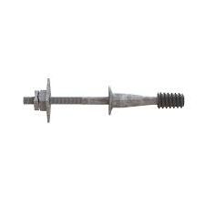
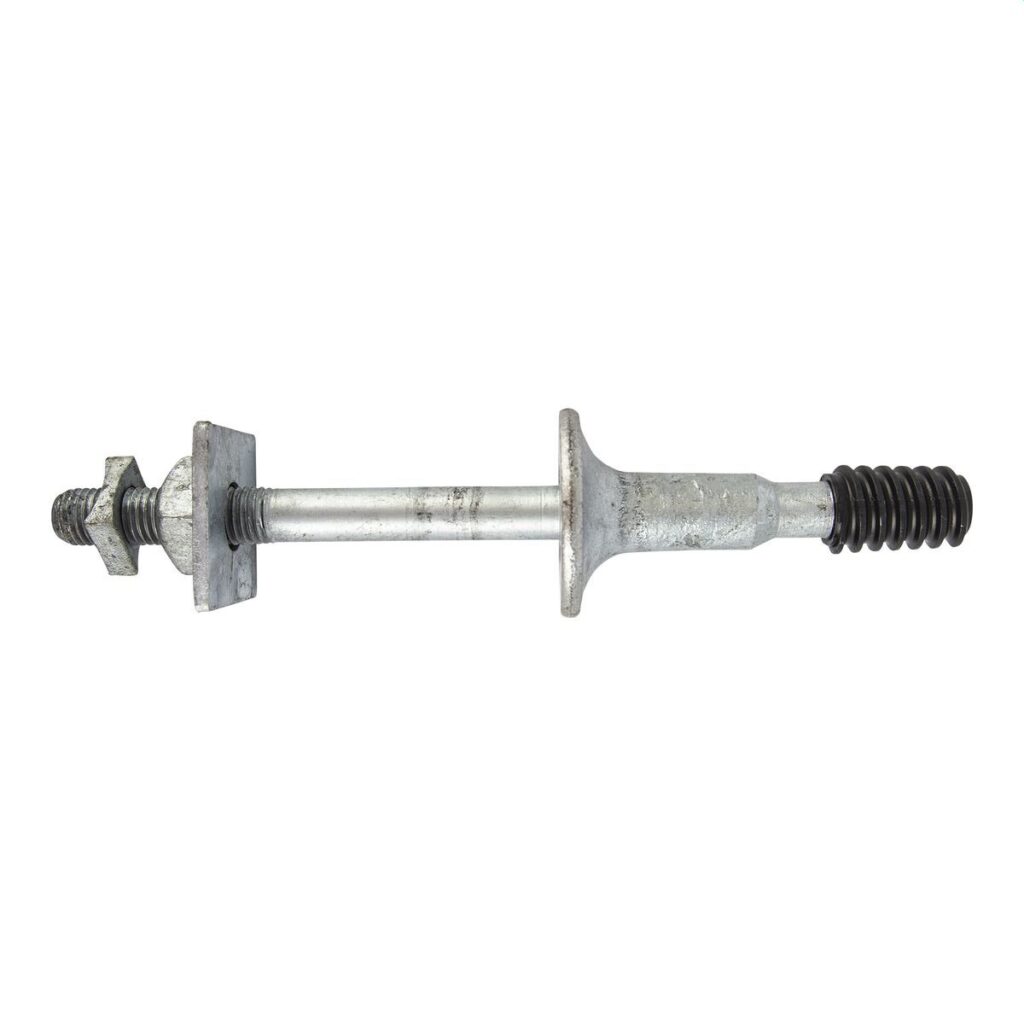
The main components of the pin work together to create a reliable and secure attachment point for insulators or other devices on he crossarm. The available design and specifications of the crossarm pin vary depending on the specific application and the load requirements of the power transmission system. The following are the main components of the crossarm pin.
- Pin body – this is the main section of the pin which has a cylindrical rod that provides support and stability.
- Mounting end – this is the part that connects to the insulator or other devices which has a threaded design to facilitate attachment and ensure a secure connection.
- Grooves – grooves help to enhance the grip and prevent rotation or loosening of the pin once it is installed in the crossarm. They provide a more secure connection between the pin and the crossarm.
- Fasteners – the fastening mechanisms secure the pin in the crossarm. They include devices such as bolts, nuts and washers to provide stability and support.
Types of crossarm pins
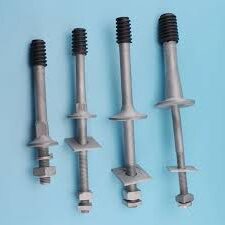
Different designs of the crossarm pin depend on factors such as the specific application requirements, the load capacity, insulator used and compatibility with other devices. Each type pf the pin has its own advantages and disadvantages to consider before selecting. The following are the common types of crossarm pins.
V-type pin – this pin has a V-shape design with two mounting points commonly used for attaching multiple insulators.
J-type pin – the J-type pin has a curved design which allows for easy installation and removal of insulators.
Threaded pin – high-strength threaded crossarm pins have threads along their shanks which allow for more secure attachment to the crossarm.
Tapered pin – the tapered pins have a gradual taper along their shank which facilitates easier insertions into the crossarm hole. It ensures a tight and secure fit which minimizes the risk of movement.
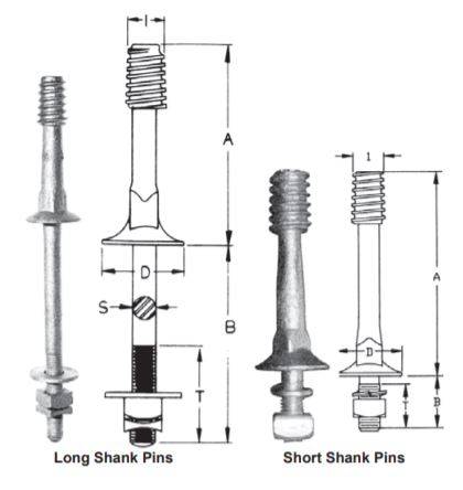
Straight shank pin – the straight shank pins have a straight shank with a tapered or threaded ends for mounting the insulator.
Square shank pin– the square shank provides additional stability and resistance to rotation compared to round shank pins.
Applications of a crossarm pin
The application areas of the crossarm pins vary depending on the regional power infrastructure, industry practices and the requirements of the particular power transmission and distribution systems. The crossarm pins are used in power transmission and distribution systems to secure insulators and other devices. The following are the main application areas of the crossarms pins.
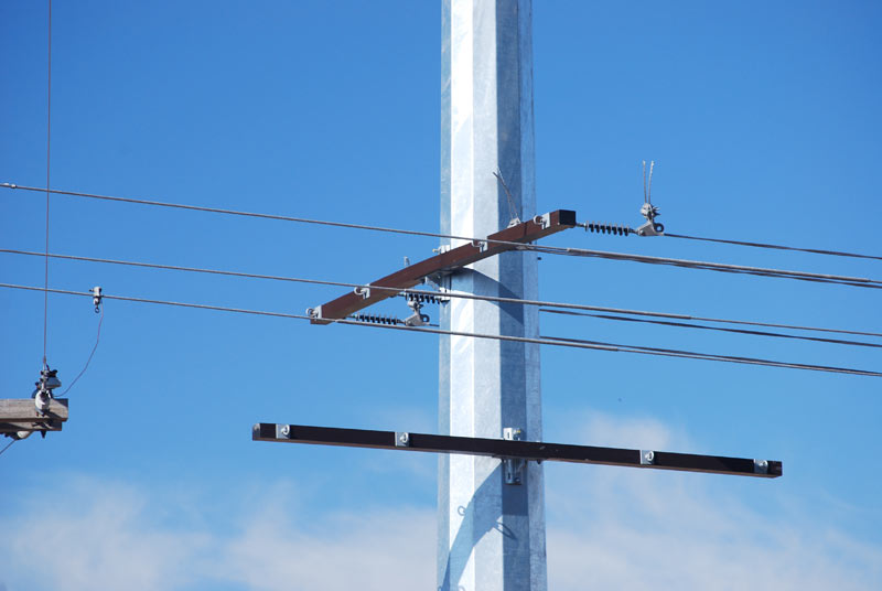
- Crossarm pins work in overhead power transmission lines to attach insulators that support power conductors to provide a secure and stable mounting point for the insulators. This ensures proper conductor alignment and electrical insulation.
- The pins also work in distribution lines to deliver electricity to residential, commercia and industrial areas. They help to attach the insulators that support the distribution conductors which enables efficient and reliable power distribution.
- Crossarm pins help in mounting of equipment and devices such as antennas or communication cables to utility poles.
- Corrosion-resistant crossarm pins help to mount insulators and other devices within the substation to support the transmission and distribution lines.
- High load capacity crossarm pins work in power generation facilities such as hydroelectric, wind or solar power plants which help to secure insulators and associated equipment to the crossarms.
- Crossarm pins help in expanding electricity access and ensures a reliable power supply in rural electrification projects.
Threaded crossarm pin Installation guide
When installing overhead lines, it is advisable to follow threaded crossarm best practices to ensure secure and reliable attachment. The process varies depending on the specific type of crossarm pin, manufacturer’s instructions and follow industry best practices for a safe and reliable installation. Additionally, it is advisable to seek assistance of qualified professionals to help ensure proper installations. The following are the basic steps involved in the installation of the crossarm pins.
- Ensure the crossarm pin is clean and free from any debris or obstructions by inspecting for damage or defects.
- Select the appropriate type and size of the pin based on the requirements of the specific application, the crossarm material and load capacity needed.
- Locate the desired position on the crossarm to install the crossarm and ensure the hole centered, aligned and vertical to the crossarm surface.
- Drill the hole using a drill on the marked location which should match the diameter of the crossarm to install.
- Insert the mounting end of the pin into the drilled hole on the crossarm and ensure the pin is fully inserted.
- Secure the crossarm pin using the available fastening mechanisms to secure the pin tightly in place.
- Inspect the installation to ensure that the pin is securely fastened, aligned properly and seated correctly in the crossarm.
Selection process of the best crossarm pin
The selection process can prove to be tedious especially when new to the industry. The selected crossarm pin should be the appropriate pin for the specific application and ensure a secure and reliable attachment to the crossarm. The selection process involves considering key factors to choose the best pin. The factors are as detailed below.
- Determine the expected load to support with the crossarm pin and consider the weight of the conductors, insulators and other attached equipment.
- Evaluate the available types of pins by considering the specific application requirements and determine the type and design suited for your project.
- Consider the level of corrosion resistance required and choose a pin made from a corrosion-resistant material or coatings.
- Evaluate the cost-effectiveness of the pin while considering the quality and performance required.
- Consider the material of the crossarm and ensure it is compatible with the material of the crossarm to ensure a secure and reliable connection.
- Consider the diameter of the pin and ensure it matches the size of the drilled hole in the crossarm.
- Ensure the pin meets the relevant industry standards and regulations to ensure safety and performance of the pin.
- Consider the reputation of the manufacturer who should provide guidance on the suitable applications, load capacities and installation requirements for their products.