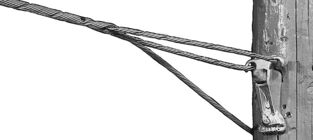
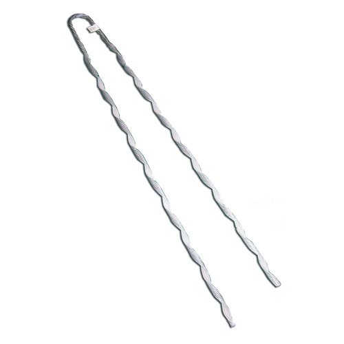
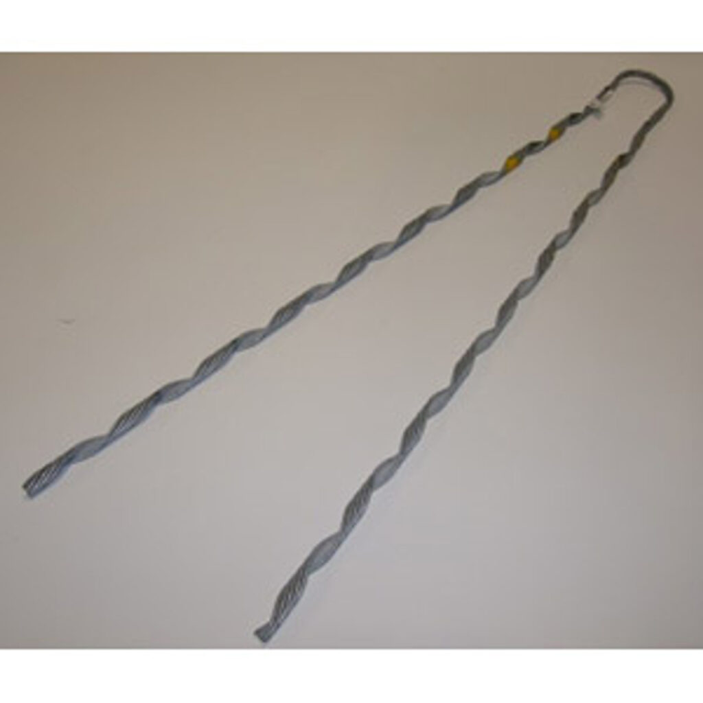
A false dead end refers to a support structure where conductors anchor but continue on the next support without ending. It creates an illusion that the line does not continue beyond that point. This is to deter animals and humans from climbing. False dead ends provide mechanical support to manage the tension and weight of the conductors. They help to maintain the integrity and stability of the transmission line. They work at points where the transmission line changes direction. The anchoring help manage extra forces and tensions at these directional shifts. This also helps to distribute the mechanical load across the entire length of the transmission line. False dead ends also allow for easier maintenance and sectioning of the line. False dead ends are from materials like steel, aluminium and composite materials.
Benefits of using a false dead end
False dead ends provide several benefits to the transmission lines. This is including enhancing the performance, reliability and maintainability of the system. The dead ends ensure the mechanical stability, durability and reliability of the transmission lines. This is by reducing sagging, distributing loads and providing extra support. The following are the common benefits of using false dead ends.
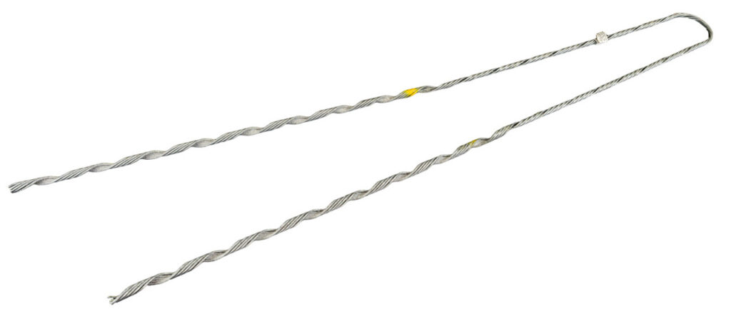
- Mechanical stability and strength – false dead ends provide support to transmission lines. This is by maintaining the conductor tensions. By anchoring the conductors, the dead end help maintain the structural integrity of the transmission system.
- Enhanced durability – use of false dead ends contribute to the durability of the transmission lines. That anchoring points help manage stresses caused by environmental factors. This is including wind, ice and temperature fluctuations.
- Improved reliability – false dead ends provide extra points of support and tension management. This helps to reduce the likelihood of conductor sagging, snapping and other failures. This helps to ensure the continuous and stable power supply in high demand areas.
- Directional changes – the dead ends provide the necessary support to handle the extra lateral forces. This helps maintain the alignment of the conductors and prevents undue stress on the support structures.
- Load distribution – the dead ends distribute the mechanical load across the entire length of the line. This helps reduce stress on individual poles to prevent potential structural failures.
- Operation flexibility – they also ease management and maintenance of the transmission line. They allow for sections of the line to isolate during repairs or maintenance.
- Reduced sagging – conductor sagging can lead to several problems. This is including reduced clearance from the ground. Use of false dead ends help maintain the proper tension in the conductors thus reducing sagging.
Performance characteristics of a false dead end
There are various ways to check the performance of the false dead end in transmission lines. The characteristics define how well false dead ends can support, stabilize and maintain the integrity of the transmission lines.Discussed below are the performance characteristics of the false dead ends.
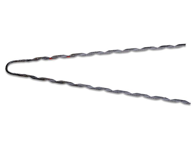
- Load bearing capacity – false dead ends must have a high load-bearing capacity. This is to handle the mechanical stresses by the conductors. They should be able to handle tensile strength and compressive strength.
- Directional stability – the dead ends should provide support to manage the lateral forces. They should ensure the structure can handle side-to side forces without bending. They should also be able to maintain the conductor alignment.
- Ease of installation and maintenance – their design should ease easy installation and maintenance. They should have components that allow easy assembly, disassembling and replacement.
- Environmental adaptability – false dead ends should perform well under various environmental conditions. They should have the ability to maintain structural integrity and performance. They should also be able to perform under adverse weather conditions. This is including winds, heavy snow or ice accumulation.
- Tension management – false dead ends have designs to manage and maintain the suitable tension in the conductors. They should prevent conductor sagging to ensure they remain taut to maintain safe clearance from the ground. They should also be able to reduce the impact of dynamic loads.
- Durability – the dead ends should be durable and capable of withstanding various environmental conditions. They should have the ability to resist corrosion from weather elements. They should be from materials like galvanized steel, aluminium alloys or other composites.
- Mechanical flexibility – They should offer some degree of flexibility to absorb and mitigate the effects of dynamic loads. This helps to reduce the impact of vibrations caused by wind or mechanical oscillations.
Tensile strength of the dead ends
Tensile strength of false dead ends is a performance characteristic that ensures they can handle the mechanical stresses. The tensile strength refers to the greatest amount of tensile force a false dead end can withstand without failing. Additionally, the strength depends on the materials used, design specifications and load ratings. Enough tensile strength is crucial for the reliability, safety and efficiency of the power network. Adequate tensile strength helps prevent mechanical failures, maintain line integrity and enhance safety of the dead ends. The following are the considerations for tensile strength of false dead ends.
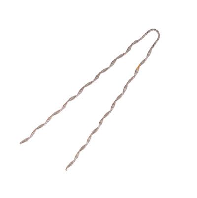
- Material composition – false dead ends are from materials like galvanized steel, aluminium alloys and composite materials. They provide high strength, durability, corrosion resistance, and high strength-to-weight ratios.
- Design specifications – false dead ends designs depend on the specific standards that dictate their tensile strength. The standards ensure they can handle the greatest expected loads.
- Load ratings – the dead ends have ratings for specific load capacities. These ratings include a safety margin to ensure reliability under greatest stress conditions.
- Standards and testing – false dead ends should follow relevant industry standards and regulations. They provide guidelines for the design and testing of the dead ends.
Testing false dead ends
Testing false dead ends ensures they meet the necessary performance standards. This is to support the mechanical loads imposed by the conductors. The testing process involves preparation, testing execution post-test analysis and certification. Testing helps to ensure safety, reliability, compliance and quality control. Also, it is important to seek professional help to understand the various testing methods. The following are the various testing methods for false dead ends.
- Tensile testing – this helps to determine the greatest tensile strength of the false dead end and ensure it can withstand the expected loads. The process involves subjecting the dead end to increasing tensile force until it breaks. This test measures the greatest force the false dead end can endure.
- Mechanical load testing – this is to check the false dead end’s ability to handle static and dynamic loads. The dead end faces forces that replicate the tension from conductors and environmental factors. The tests check for deformations, cracking or other signs of failure under load.
- Fatigue testing – this is to assess the durability of the false dead ends under repeated loading and unloading cycles. The dead end subjects to cyclic loading to simulate the stresses encountered during its service life.
- Environmental testing – this is to ensure the dead ends can withstand various environmental conditions. It involves placing the components to environmental chambers that simulate different weather conditions.
- Vibration testing – this test it to check the false dead ends resistance to vibrations caused by wind or other forces. The method is to assess its stability and integrity under oscillatory forces.
- Electrical testing – this is to ensure the maintenance of electrical insulation properties. It involves measuring the electrical resistance and breakdown voltage to ensure the false dead ends.
Certifications and standards for false dead ends
The certification process involves design and manufacturing compliance, testing and evaluation, certification issuance, ongoing compliance and quality control. Certification ensures the false dead ends can handle the mechanical loads and environmental conditions. They also show a commitment to high-quality manufacturing processes and continuous improvement. The following are the certifications and standards the false dead ends adhere to.
- IEEE standards – these include guides for the design and testing of transmission line hardware. They also include standard test procedures for the thermal evaluation of solid electrical insulation.
- IEC standards – this specifies the mechanical and environmental performance tests for false dead ends.
- ANSI standards – this includes standards for the performance and testing of mechanical connectors.
- ISO standards – these are quality management systems that ensure the manufacturing processes for false dead ends adhere to high-quality standards.
- ASTM standards – these are standards that ensure corrosion resistance for metallic components.
Frequently asked questions
False dead ends provide benefits like mechanical stability, improved load distribution, increased durability and operational flexibility.
Performance characteristics include high load bearing capacity, effective tension management, directional stability and mechanical flexibility to absorb dynamic loads.
The dead ends undergo tensile testing, mechanical load testing, fatigue testing, vibration testing and electrical testing.
False dead ends adhere to several certifications like IEEE standards, IEC standards, ANSI standards and ISO certifications.